Where possible, the old original jarrah roof timbers removed to make room for the top storey are being recycled back into the house by way of the staircase, window sashes, and many other uses. Most of the straight treads in the stair case are made from glued up rafters from the original roof.
Yep, it ticks all the right boxes...
Previous posts tell the story of the Staircase Saga thus far:
Part 1: Building a Staircase with Winders.
Part 2: Getting Started.
Part 3: The Big Flight.
Part 4: The Short Flight.
Part 5: The Winders.
It seems that somehow I don't have a pic of the staircase with the winders completed which shows the missing first two treads.
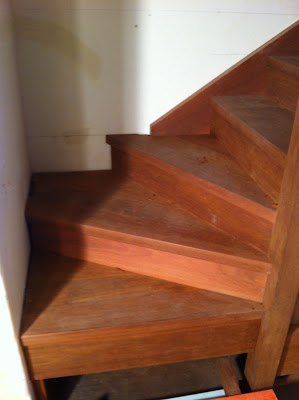 |
| Winders completed... now for the first two treads. |
| The original architect's plan, showing the first two treads poking straight into the entry hall. |
In the original plan, these first two treads were going to stick straight into the entry hall. Discussing this one day, we hit on the idea of making these treads flow out into the room by both curving around to meet the walls on either side. It seemed like a really good idea! Another fantastic challenge for me, and I was looking forward to bringing the concept to reality.
Planning the curving treads.
If you have been following this saga, you won't be surprised to find I start out with a set-out board with a full scale drawing. It was important first to transfer the positions of the newel posts, walls and other key features onto this board. In this house which is 80 years old, not many of the original walls and floors are square or plumb. I needed to record all this on the set-out board, as everything would need to be scribed to fit the existing floors, walls, and staircase structure.
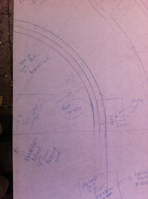 |
| Part of the full scale drawing board, showing the right hand end. |
Formers, riser boards, and nosings.
I needed to decide upon the method to be used to make the curved riser boards. Years ago, I used the multi-kerf method to bend jarrah sides for a couple of coffins I built. I reckon that would be the way to do this. So I did some testing.
 |
| A rough test, but it was going to be a winner. |
 |
| Cutting the kerfs with the radial arm saw. |
The formers were made using 16mm (5/8") plywood and bits of jarrah.
 |
| Making up the former for Tread 1's riser board. |
 |
| Former with lining blocks ready to have the riser board attached. |
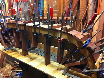 |
| You can never have too many cramps! Gluing the riser board to the former. |
 |
| Gluing a couple of layers of thick jarrah veneers to the back of the bottom edge of the riser board. |
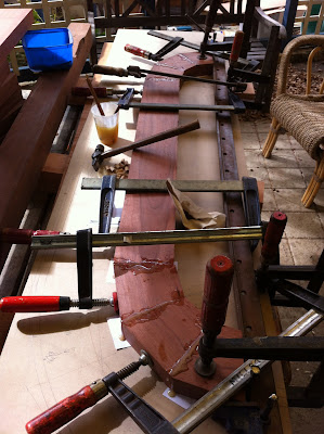 |
| The nosing for Tread 1 being glued up in its segments. |
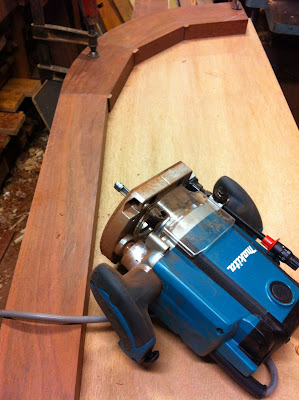 |
| Accurate templates and the router with a long flush-cut bearinged bit would cut the sweeping curves in the nosing. |
 |
| The rebate cut on the inside would hold the tread insert behind the nosing. |
 |
| The groove cut on the underside of the nosing, to house the riser board. |
 |
| The two tread units completed and placed in their stack - except for the inserts. |
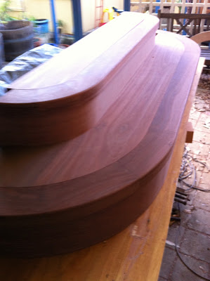 |
| Tread inserts cut to fit. Time to do the installation! |
Installing the two tread units.
First I had to sand the floor in the immediate area to get the floor area ready.
Then I had to scribe the bottom unit (Tread 1) to the floor and walls.
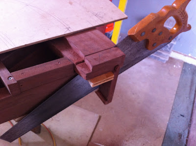 |
| Cutting the horns to length to achieve a snug fit to the walls. |
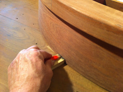 |
| Scribing the riser board to follow the contour of the floor. |
 |
| The inserts being fitted to the treads. These were nailed into place. |
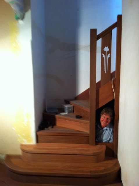 |
| It's no wonder I'm smiling!! ...All treads now completed. |
Righto. Now it's time to contemplate the handrail and wall trim...
I guess I'd better make the door for the hidie-hole too!
.jpg)
